 Series J13 flanged single sphere rubber expansion joint is designed to compensate various movements in pipeline, such as the movements by heat-generated expansions, settlements of terrain or building structures, rolling movements and assembly errors, machinery vibrations, water hammers, etc. Series J13 flanged single sphere rubber expansion joint is designed to compensate various movements in pipeline, such as the movements by heat-generated expansions, settlements of terrain or building structures, rolling movements and assembly errors, machinery vibrations, water hammers, etc.
FEATURES • All rubber compounds for lining are specifically formulated to provide maximum sound and heat insulation as well as abrasion resistance
• A strong, bias-ply construction, high-strength nylon fabric inside rubber Round steel rings embedded in the liner give maximum strength to the expansion joint while under pressure or vacuum service
• Flanges are full-faced and make an integral part of the joint to insure a tight reliable seal, no gasket are necessary 
 
 
| Connection | Flanged PN16, PN10, PN6 | | Nominal diameter | DN25-DN1600 | | Pressure rating | PN16 for DN25-DN300, PN10 for DN350-DN600, PN6 for DN700-DN1600 | | Vacuity | 750mmHg for DN25-DN300, 500mmHg for DN350-DN600, 300mmHg for DN700-DN1600 | | Temperature range | -20°C to +200°C(depending on rubber material) |

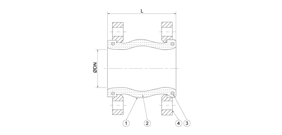
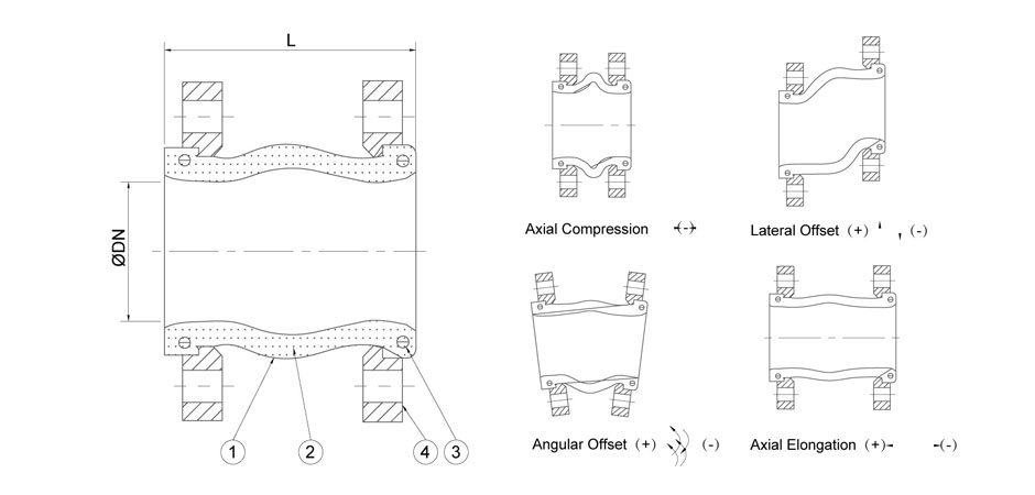
| No. | Part name | Material | | 1 | Rubber | EPDM, CR, NBR, FPM | | 2 | Fabric | Nylon | | 3 | Retaining rings | Galvanized steel | | 4 | Flanges | Galvanized steel |

| SIZE | L | Axial shift | Lateral shift | Angular shift | | DN | INCH | Stretch | Compression | | 25 | 1" | 95 | 6 | 9 | 9 | 15° | | 32 | 1 1/4" | 95 | 6 | 9 | 9 | 15° | | 40 | 1 1/2" | 95 | 8 | 10 | 9 | 15° | | 50 | 2" | 105 | 8 | 10 | 10 | 15° | | 65 | 2 1/2" | 115 | 8 | 15 | 12 | 15° | | 80 | 3" | 135 | 8 | 15 | 12 | 15° | | 100 | 4" | 150 | 12 | 19 | 15 | 15° | | 125 | 5" | 165 | 12 | 20 | 15 | 15° | | 150 | 6" | 180 | 16 | 28 | 15 | 15° | | 200 | 8" | 190 | 16 | 28 | 22 | 15° | | 250 | 10" | 230 | 16 | 28 | 22 | 15° | | 300 | 12" | 245 | 16 | 28 | 25 | 15° | | 350 | 14" | 265 | 16 | 28 | 25 | 15° | | 400 | 16" | 265 | 16 | 28 | 25 | 15° | | 450 | 18" | 265 | 16 | 28 | 25 | 15° | | 500 | 20" | 265 | 16 | 28 | 25 | 10° | | 600 | 24" | 265 | 16 | 28 | 25 | 10° | | 700 | 28" | 260 | 16 | 30 | 25 | 10° | | 800 | 32" | 260 | 16 | 30 | 25 | 10° | | 900 | 36" | 260 | 16 | 30 | 25 | 10° | | 1000 | 40" | 260 | 16 | 30 | 25 | 10° | | 1200 | 48" | 260 | 16 | 30 | 25 | 10° | | 1400 | 56" | 300 | 16 | 30 | 25 | 10° | | 1600 | 64" | 300 | 16 | 30 | 25 | 10° |
| Connection | Flanged PN16, PN10, PN6 | | Nominal diameter | DN25-DN1600 | | Pressure rating | PN16 for DN25-DN300, PN10 for DN350-DN600, PN6 for DN700-DN1600 | | Vacuity | 750mmHg for DN25-DN300, 500mmHg for DN350-DN600, 300mmHg for DN700-DN1600 | | Temperature range | -20°C to +200°C(depending on rubber material) |
 Series J13 flanged single sphere rubber expansion joint is designed to compensate various movements in pipeline, such as the movements by heat-generated expansions, settlements of terrain or building structures, rolling movements and assembly errors, machinery vibrations, water hammers, etc. Series J13 flanged single sphere rubber expansion joint is designed to compensate various movements in pipeline, such as the movements by heat-generated expansions, settlements of terrain or building structures, rolling movements and assembly errors, machinery vibrations, water hammers, etc.
FEATURES • All rubber compounds for lining are specifically formulated to provide maximum sound and heat insulation as well as abrasion resistance
• A strong, bias-ply construction, high-strength nylon fabric inside rubber Round steel rings embedded in the liner give maximum strength to the expansion joint while under pressure or vacuum service
• Flanges are full-faced and make an integral part of the joint to insure a tight reliable seal, no gasket are necessary 


| No. | Part name | Material | | 1 | Rubber | EPDM, CR, NBR, FPM | | 2 | Fabric | Nylon | | 3 | Retaining rings | Galvanized steel | | 4 | Flanges | Galvanized steel |

| SIZE | L | Axial shift | Lateral shift | Angular shift | | DN | INCH | Stretch | Compression | | 25 | 1" | 95 | 6 | 9 | 9 | 15° | | 32 | 1 1/4" | 95 | 6 | 9 | 9 | 15° | | 40 | 1 1/2" | 95 | 8 | 10 | 9 | 15° | | 50 | 2" | 105 | 8 | 10 | 10 | 15° | | 65 | 2 1/2" | 115 | 8 | 15 | 12 | 15° | | 80 | 3" | 135 | 8 | 15 | 12 | 15° | | 100 | 4" | 150 | 12 | 19 | 15 | 15° | | 125 | 5" | 165 | 12 | 20 | 15 | 15° | | 150 | 6" | 180 | 16 | 28 | 15 | 15° | | 200 | 8" | 190 | 16 | 28 | 22 | 15° | | 250 | 10" | 230 | 16 | 28 | 22 | 15° | | 300 | 12" | 245 | 16 | 28 | 25 | 15° | | 350 | 14" | 265 | 16 | 28 | 25 | 15° | | 400 | 16" | 265 | 16 | 28 | 25 | 15° | | 450 | 18" | 265 | 16 | 28 | 25 | 15° | | 500 | 20" | 265 | 16 | 28 | 25 | 10° | | 600 | 24" | 265 | 16 | 28 | 25 | 10° | | 700 | 28" | 260 | 16 | 30 | 25 | 10° | | 800 | 32" | 260 | 16 | 30 | 25 | 10° | | 900 | 36" | 260 | 16 | 30 | 25 | 10° | | 1000 | 40" | 260 | 16 | 30 | 25 | 10° | | 1200 | 48" | 260 | 16 | 30 | 25 | 10° | | 1400 | 56" | 300 | 16 | 30 | 25 | 10° | | 1600 | 64" | 300 | 16 | 30 | 25 | 10° |
|


 Fl anged Single Sphere Rubber Expansion Joints ★★★